 FD H40
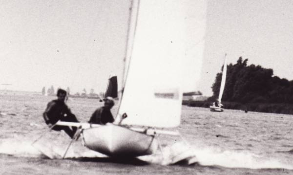
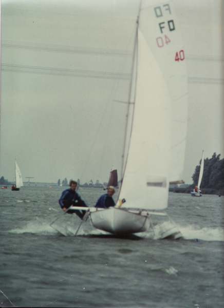
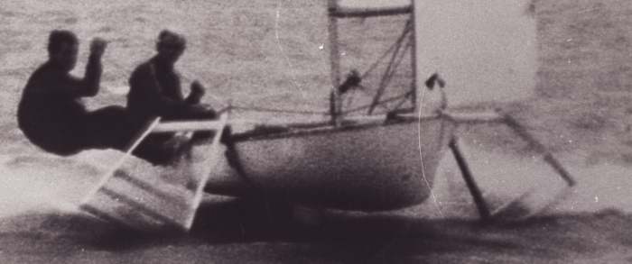
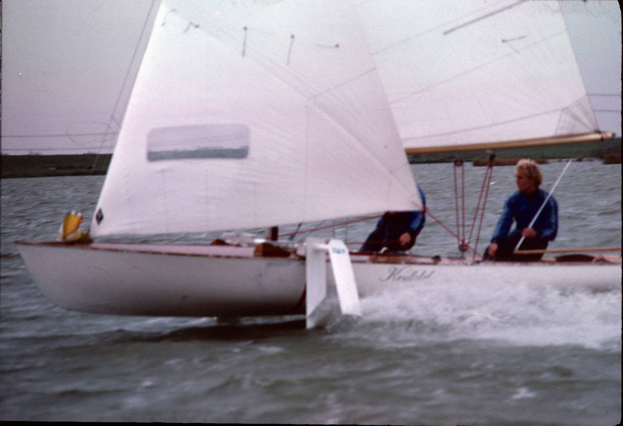
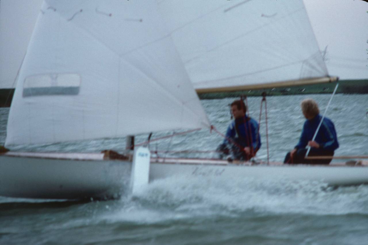
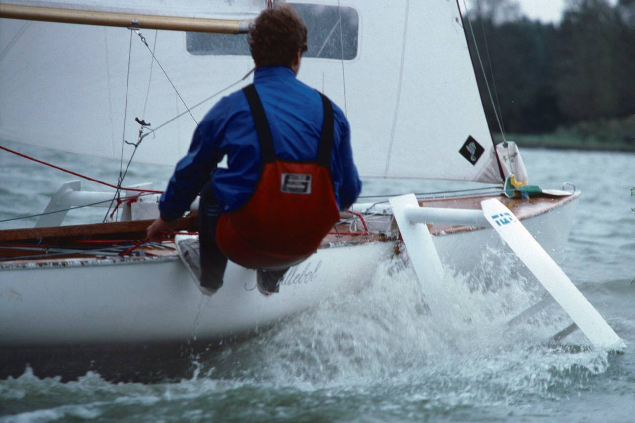
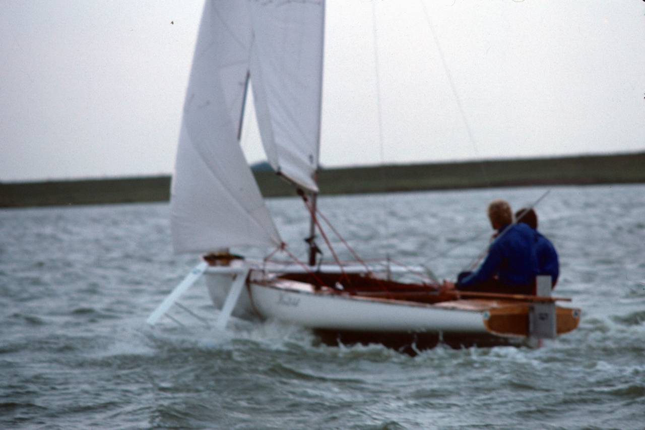
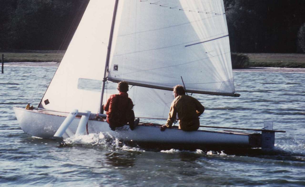
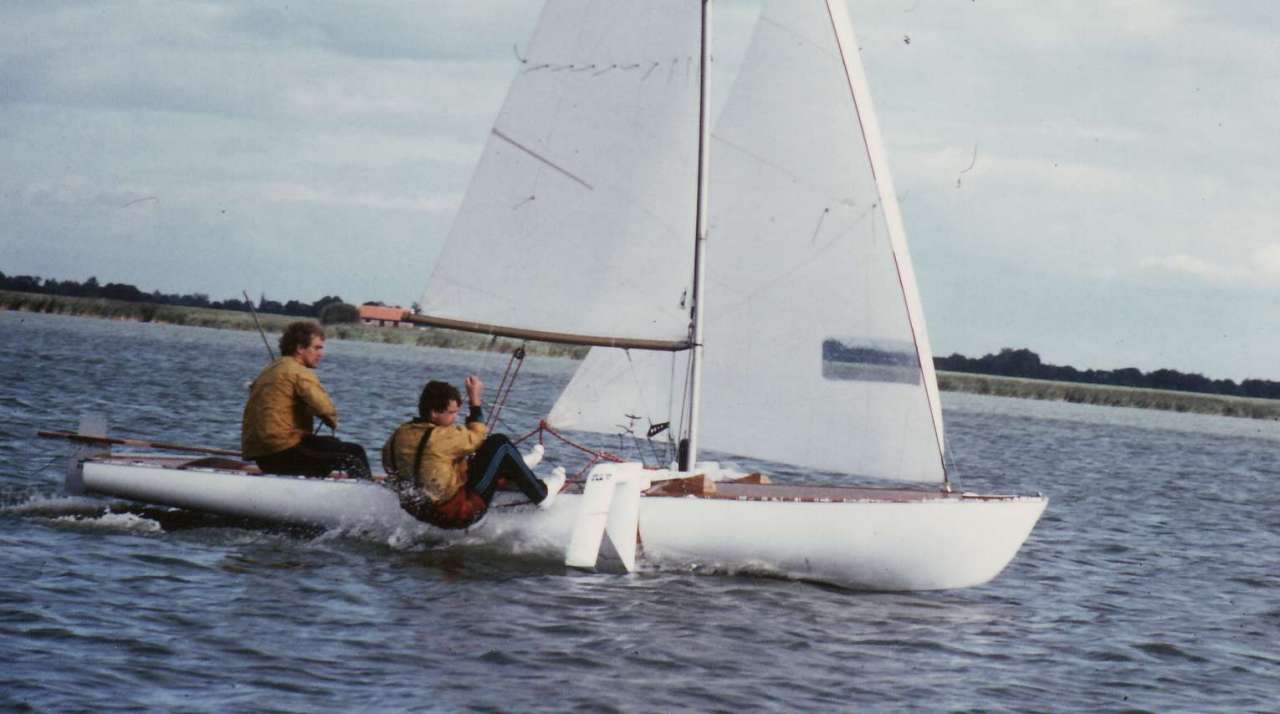
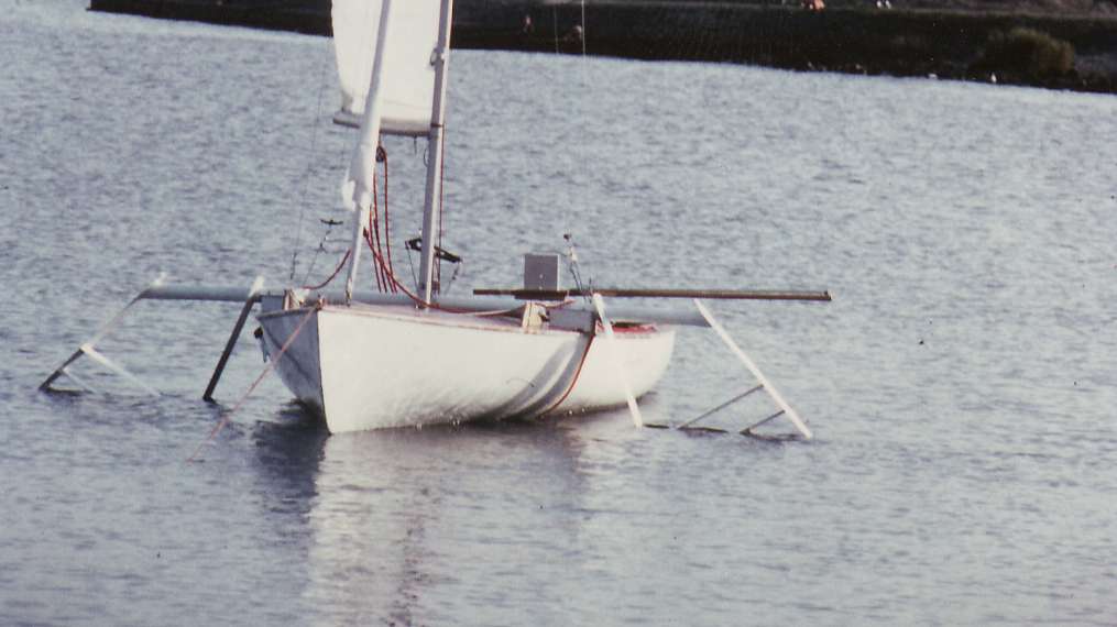
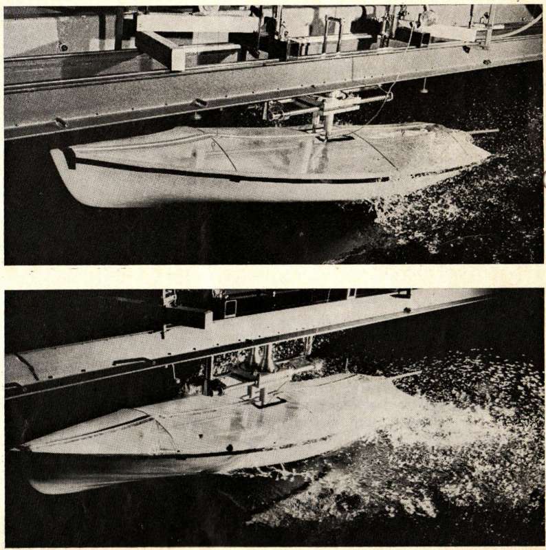
Flying Dutchman H40 on hydrofoils in 1980, an experiment to increase the max speed of a single hulled sailboat.
#@hanno; May 1980 Back »


Improvements for the future are:
Decrease the mass, by attaching the foils to a single hull. Sail alone. Decrease the cordlength at the tip of the foils. Make a better device to control the angle of attack of the rear foil.
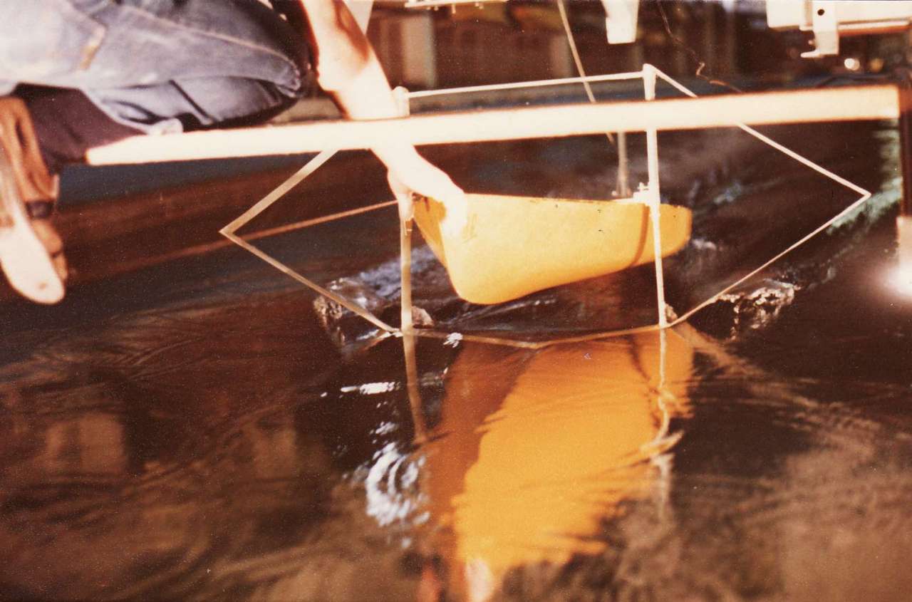
We started with some good basic tank testing. Some of the real results are presented on this webpage.
The test were done at the model basin of the Delft University of Technology. In 1978 Hanno Smits and Freek Verkerk, performed the tests as part of their fourth year thesis. The tests were necessary for the design for full-scale foils and tests with the then still olympic Flying Dutchman class sailboat. The proof of these full-scale test were shown in the hydrofoil and speedsailing page.
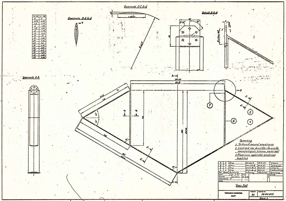
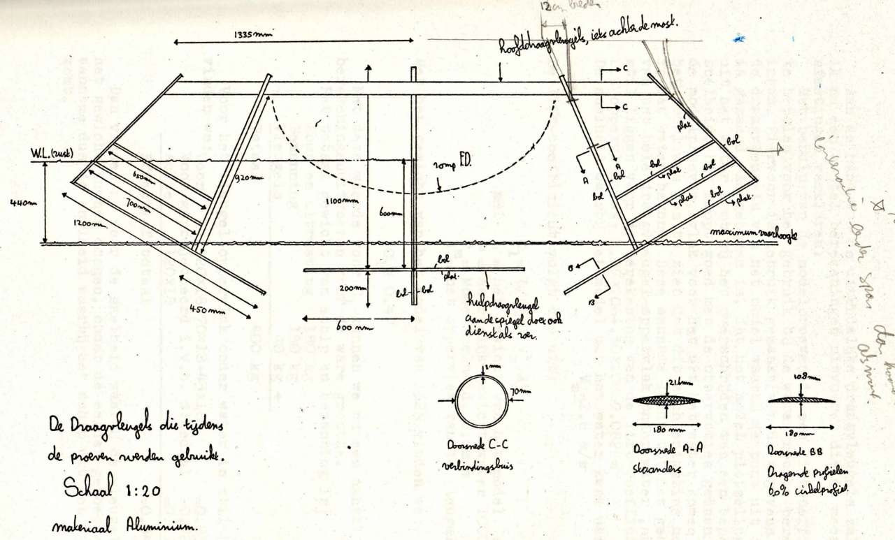
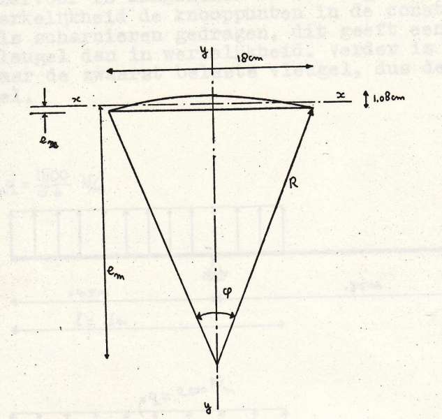
For the tests we decided to use a so-called circular section of 6% thickness/cordlength ratio. The reason for the selection of this section was, reduction of ventilation ( a sharply pointed section has a less pronounced suction-peak near the tip and consequently is less susceptible to ventilation). Secondly this section is easy to constuct.
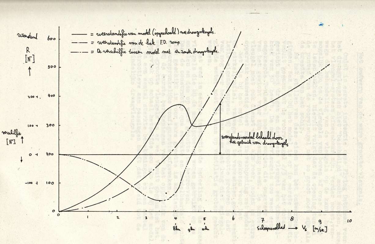
At the Delft University our professor ir. J.Gerritsma had already tested a Flying Dutchman type sailboat. The scale of the model was 1:3. (All resistance values should be multiplied by 9 and the speed values by 1.73 to get the full scale values; Froude Law)
We did want to end up with realistic foil dimensions so for a 6% thickness-ratio foil we selected a cordlength of 15 cm for the full scale system. In full scale the thickness then is only 0,9cm, an absolute minimum for strength. Remember in 1980 carbon-fibre (dyneema and what have you) was not readily available, and little experience in construction techniques was available, we opted for aluminium construction. In the model the foils were polyester-plate with a 3cm cordlength and only 0,45cm thickness, resulting in foil less stiff than we wanted for our design and tests.
As a consequence of this we decided to test with a V-shaped front-foil where starboard and port foil connected, under the hull. Our main objective was determine the Cl, CD values of a foil system. The rear foil was a T-shaped foil.
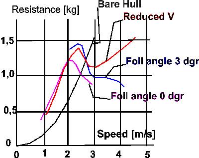
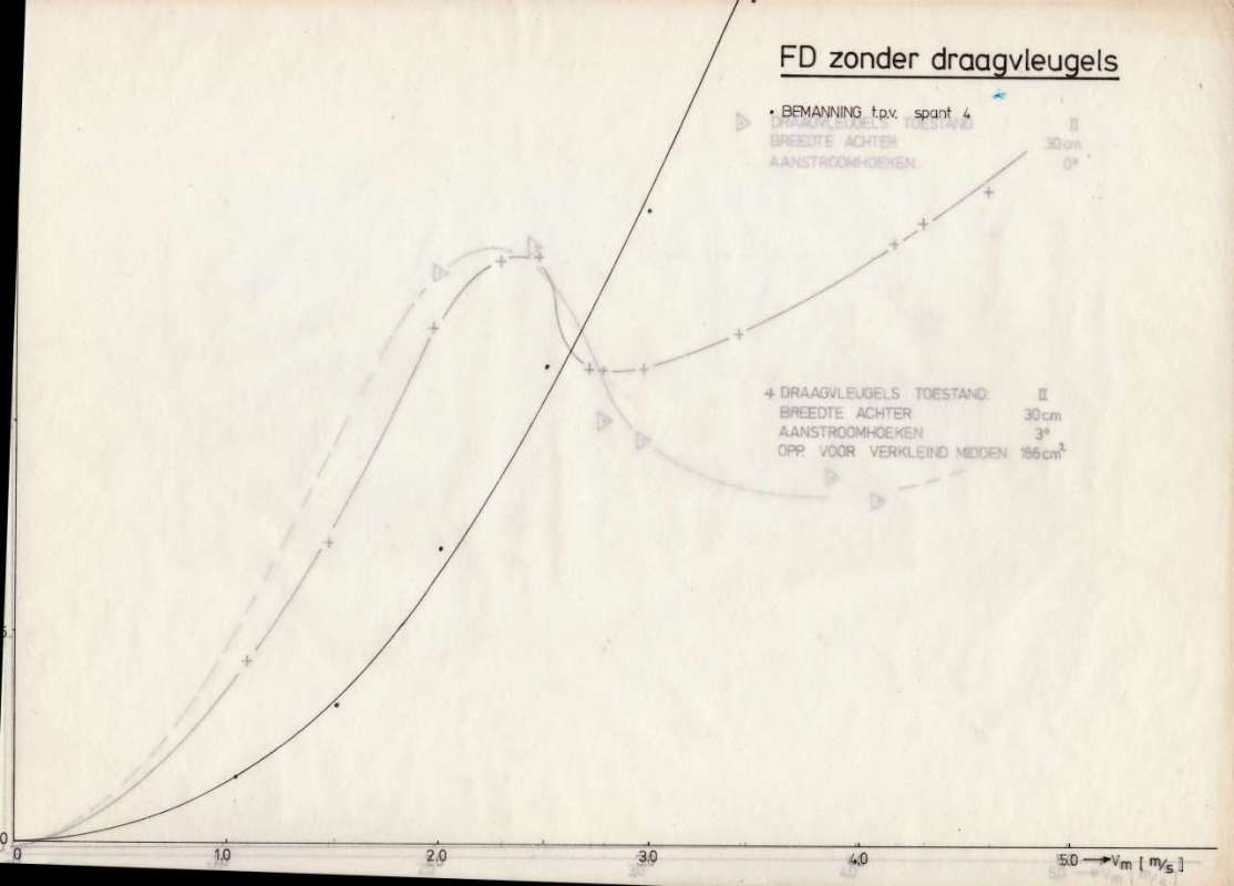
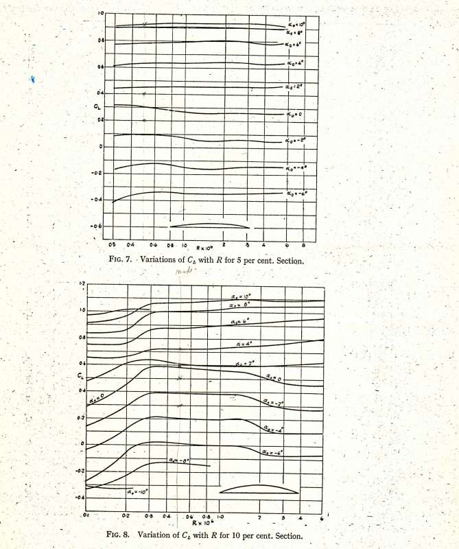
The graph shows for example two graphs with different angle of attack of the foils while the model was at rest. Particularly the case of 0 degrees shows that a rear-foil with a low angle of attack results in a lower drag and the consequental higher speed. We also found this in the full scale tests.
The determination of the Cl Cd values was important because it also tells you something about the balance between the front and the rear foils and about the decrease in efficiency of the foils when approaching the surface.
For the calculation of the Cl Cd values we used photographs to determine the submerged foil-area.
The average Cd value when on foils did not vary very much, between the different configurations. The same is true for the lift-coefficient Cl for the front foil. The rear foil had a much lower CL and Cd in the 0 degrees angle of attack situation, which proved to be best for resistance reduction.
Cl range: 0,50 - 0,57
Cd range: 0,033 - 0,038
Cl/Cd app. 15
All data is real and can be used for reference as long as the source is quoted.
The "flight"-height has always been a bit low, so I would mount the foils deeper. This would require the hull to be modified, but so be it.
Secondly I would change the shape of the tips of the frontfoils to de-sensitize the ride-height/speed dependency.
Thirdly the steering is a bit too vague so the underwater area would have to be increased, by something better than the slide-on thingy we made now.
Basically the system worked very well but needed a second design iteration to make it interesting enough.

